描述
Product Description
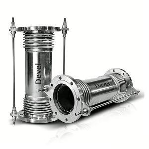
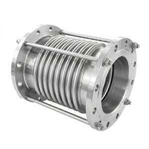
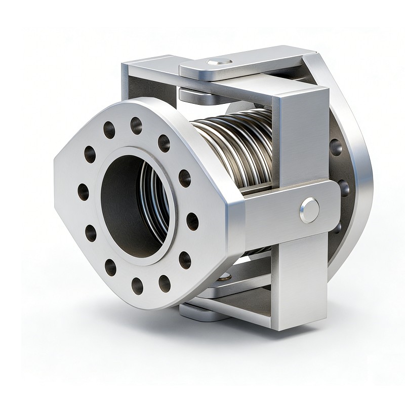
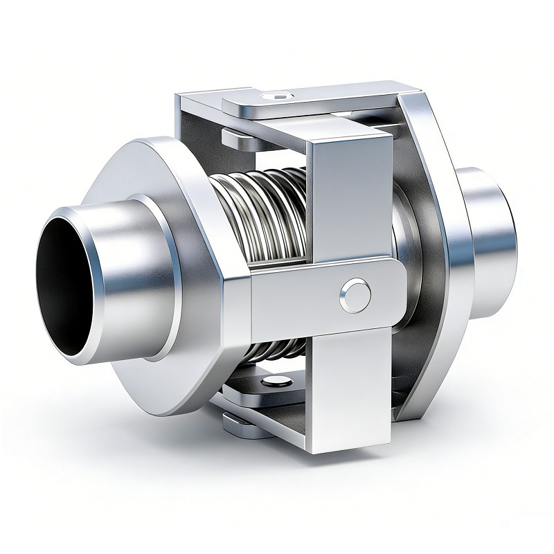
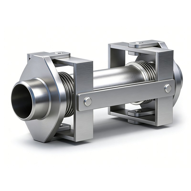
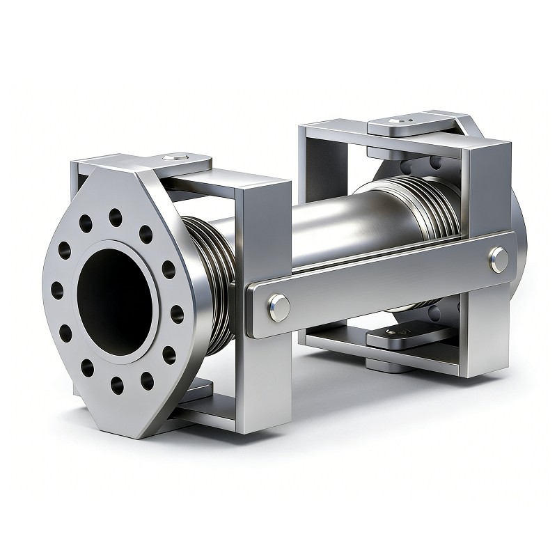
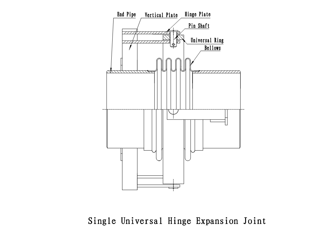
The Universal Gimbal Type Expansion Joint is a precision-engineered flexible assembly consisting of a gimbal ring, cross-pins, hinge plates, and bellows. It is designed to absorb angular rotation in any plane while utilizing the robust gimbal structure to restrain pressure thrust, ensuring the structural integrity of complex piping systems.
Technical Highlights
- Multi-directional Absorption: Accommodates angular movement in any direction within a 360-degree range.
- Pressure Thrust Restraint: The rigid gimbal structure withstands internal pressure thrust, eliminating the need for heavy-duty main anchors.
- Corrosion & Temperature Resistance: Premium stainless steel materials (SS304/316L/321) ensure reliability in extreme temperatures and corrosive media.
Product Features
- Absorb Angular Rotation in Any Plane: Through the gimbal ring structure, it can compensate for angular movement in any direction within a 360-degree spatial range.
- Restrain Pressure Thrust: The robust hinge and pin design is capable of restraining the pressure thrust forces, protecting downstream equipment.
- High Durability: Designed with multi-ply bellows construction for longer fatigue life and enhanced safety.
- Reduced Maintenance Costs: Stable structure with no need for periodic adjustment or maintenance of seals, ideal for inaccessible installation locations.
Application Areas
- Petrochemical Industry: High-temperature and high-pressure pipelines in oil refineries and chemical plants.
- Power Generation: Steam systems in power plants and gas turbine exhaust systems.
- Municipal Engineering: Protection for areas with severe ground subsidence or in active seismic zones.
- District Heating: Large-span thermal heating pipe networks.
Technical Specification Template
| Property | Description |
|---|---|
| Diameter Range | DN50 – DN3000 |
| Pressure Rating | PN6 – PN25 / Class 150 – 600 |
| Bellows Material | SS304, SS316L, SS321, Inconel |
| Connection Type | Flanged / Butt-welded |
Parameter List
| Nominal Diameter (DN) |
Number of convolutions (n) |
Install Length* Weld end (mm) |
Install Length* Flange end (mm) |
Max Outer Diameter O.D. (mm) |
Angular Movement ±(°) |
|
|---|---|---|---|---|---|---|
| mm | inch | |||||
| 200 | 8 | 4 | 650 | 670 | 560 | 2.5 |
| 250 | 10 | 4 | 650 | 674 | 710 | 2.5 |
| 300 | 12 | 4 | 700 | 774 | 810 | 2.5 |
| 350 | 14 | 4 | 700 | 774 | 900 | 2.2 |
| 400 | 16 | 4 | 700 | 774 | 980 | 1.9 |
| 450 | 18 | 4 | 900 | 874 | 1150 | 1.7 |
| 500 | 20 | 4 | 900 | 874 | 1280 | 1.6 |
| 600 | 24 | 4 | 950 | 1024 | 1350 | 2.2 |
| 700 | 28 | 4 | 1000 | 1124 | 1400 | 2.2 |
| 800 | 32 | 4 | 1000 | 1124 | 1500 | 1.5 |
| 900 | 36 | 4 | 1100 | 1224 | 1730 | 1.8 |
| 1000 | 40 | 4 | 1100 | 1224 | 2000 | 1.6 |
Note: *Install length based on the Devel factory standard. Other lengths can be changed according to your requirement.