描述

Product Overview
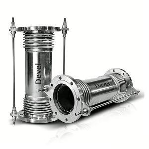
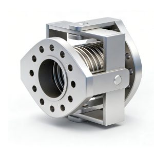
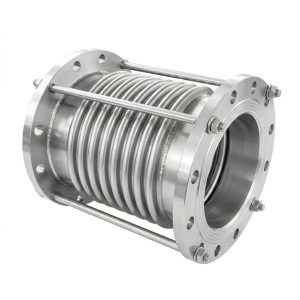
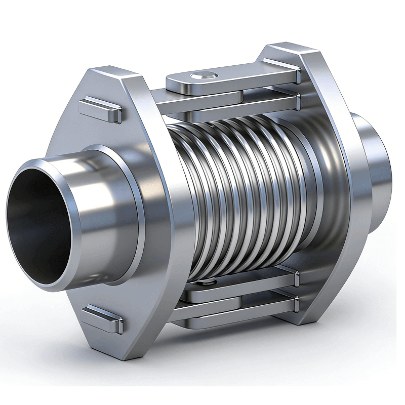
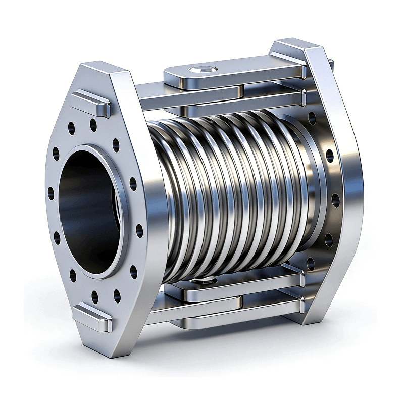
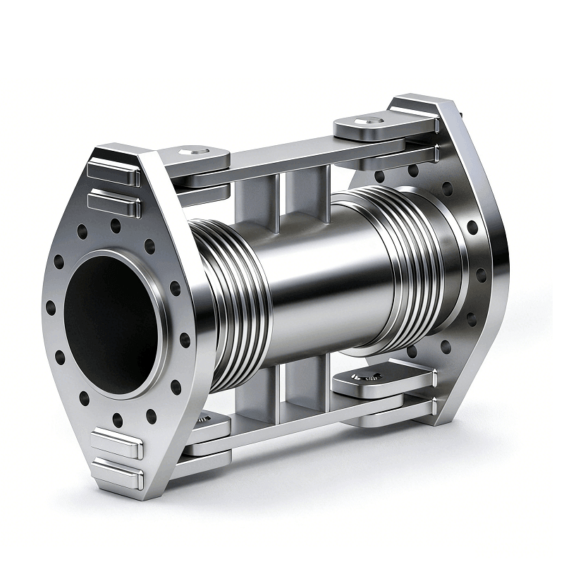
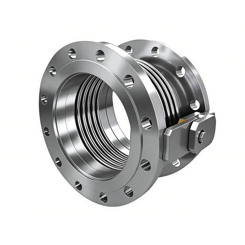
The Hinged Type Stainless Steel Expansion Joint (also known as a Single-plane Hinged Bellows) is an essential pressure-balanced component in piping systems. It primarily consists of a bellows, hinge plates, pins, and end pipes or flanges.
This product achieves angular displacement absorption in a single plane through the rotation of the hinge pins. Unlike standard bellows, the robust metal frame of the hinged type possesses high mechanical strength, capable of fully restraining the internal pressure thrust (blind plate force). This feature significantly reduces the load requirements for main anchors at the pipe ends, simplifying piping design and substantially lowering civil engineering costs.
Technical Advantages
- Pressure Thrust Restraint: The robust hinge assembly withstands the full force of internal pressure, eliminating the need for heavy-duty main anchors.
- Torsional Protection: The rigid frame structure prevents bellows from dangerous torsional deformation, significantly extending service life.
- Structural Stability: Precision pins ensure the bellows only experiences pure angular deflection, providing superior reliability.
- Premium Materials: Utilizing top-grade SS304, SS316L, or SS321 for exceptional resistance to corrosion and extreme temperatures (-196°C to +800°C).
Applications
- Petrochemical: Refinery pipelines and connections between towers and piping.
- Power Generation: Boiler piping and gas turbine exhaust systems.
- District Heating: Long-distance thermal networks to manage displacement at pipe junctions.
Installation Guidelines
- Alignment: Ensure the hinge rotation plane is aligned with the pipeline’s intended displacement direction.
- No Disassembly: Pins are factory-set; do not disassemble hinges during installation to maintain pressure integrity.
Product Parameters
| Key Specifications | Details |
|---|---|
| Nominal Diameter | DN50 – DN3000 (2″ – 120″) |
| Pressure Rating | PN1.0 / 1.6 / 2.5 / 4.0 / 6.4 MPa |
| Movement Capacity | ±5° to ±15° Angular (Customizable) |
| Design Standards | EJMA, GB/T 12777, ASME VIII-1 |
| Connection Types | Flanged or Butt-welded |
Dimensional Specifications
| Nominal Diameter(DN) | Number of convolutions (n) |
Install Length* Weld end (mm) |
Install Length* Flange end (mm) |
Max Outer Diameter O.D. (mm) |
|
|---|---|---|---|---|---|
| mm | inch | ||||
| 200 | 8 | 4 | 650 | 670 | 560 |
| 250 | 10 | 4 | 650 | 674 | 620 |
| 300 | 12 | 4 | 750 | 774 | 710 |
| 350 | 14 | 4 | 750 | 774 | 760 |
| 400 | 16 | 4 | 750 | 774 | 810 |
| 450 | 18 | 4 | 850 | 874 | 860 |
| 500 | 20 | 4 | 850 | 874 | 930 |
| 600 | 24 | 4 | 1000 | 1024 | 1090 |
| 700 | 28 | 4 | 1100 | 1124 | 1190 |
| 800 | 32 | 4 | 1100 | 1124 | 1290 |
| 900 | 36 | 4 | 1200 | 1224 | 1410 |
| 1000 | 40 | 4 | 1200 | 1224 | 1550 |
| 1100 | 44 | 4 | 1300 | 1424 | 1690 |
| 1200 | 48 | 4 | 1400 | 1424 | 1790 |
Note: *Install length based on the Devel factory standard. Other lengths can be changed according to your requirement.